

Service Overview
Even a well-manufactured insulation material can underperform when it is installed with gaps, damaged surfaces, incorrect overlaps or poorly sealed penetrations. Our installation technical-guidance service helps contractors and project teams understand the product-specific practices that protect thermal, reflective and moisture-control performance. Support can be provided remotely through drawings, photographs, video meetings and installation records, with project visits considered separately where practical and agreed. The service is particularly relevant to foil-faced roof and wall insulation, reflective membranes, reinforced facings, flexible fiberglass composites and other roll-form materials supplied by our factory. Guidance is based on the supplied product and the information available about the assembly. Because structural design, fire engineering and code compliance remain the responsibility of the project’s qualified professionals, our role focuses on material handling, orientation, joining, protection and common installation risks. Early coordination helps turn the product specification into a repeatable site procedure.
Pre-Installation Review
Before installation begins, we review available drawings and clarify where the insulation or facing sits within the roof, wall, duct or equipment assembly. The team should confirm substrate condition, framing spacing, direction of installation, required air gaps, overlap dimensions, fastening method, sealing accessories and interfaces with other materials. Site temperature, wind, rain and storage conditions may affect whether work should proceed. Roll widths and lengths can be compared with the installation grid to reduce unnecessary joints and waste. Penetrations, corners, ridges, eaves, openings and transitions deserve particular attention because they interrupt otherwise continuous layers. If the product has a reflective side, vapor-control function or designated exposed face, orientation must be understood before cutting starts. A short pre-installation checklist and sample area can reveal drawing conflicts or handling problems while corrections are still inexpensive. This stage also identifies questions that must be returned to the project designer.
Storage, Handling and Preparation
Foil surfaces and composite layers should be protected from puncture, crushing, standing water, contamination and careless dragging. Rolls need stable, dry storage and should be handled in a way that does not deform cores or damage edges. The installation area should be cleared of sharp projections, loose fasteners and debris. Cutting tools must be appropriate to the product and kept sharp so edges remain clean. The team should plan roll movement and lifting rather than opening packaging in an unsuitable location. Where adhesives or sealing tapes are used, surfaces should be clean and compatible, and application conditions should follow the accessory supplier’s instructions. Materials should be checked against labels and project requirements before use. Separating damaged rolls and recording batch information improves traceability. These simple preparations reduce visible defects, weak seams and lost time, and they are especially important for thin barrier layers whose performance depends on continuity rather than bulk thickness.
Laying, Joining and Detailing
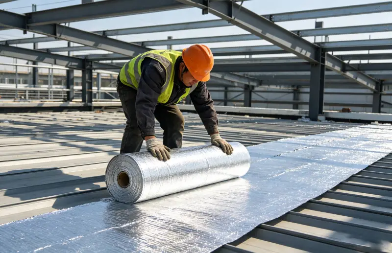
Installation guidance explains how to maintain a continuous functional layer across the main field and at details. Depending on the product and approved design, rolls may be laid parallel or perpendicular to framing, temporarily held, mechanically fastened or integrated with panels. Sheets should remain flat and reasonably tensioned without being stretched to the point of damage. Overlaps need consistent width, and seams that form part of an air or vapor-control layer should be sealed with a compatible tape or system approved for the application. Fasteners should not tear the facing, and washers or battens may be required by the project design. At corners and penetrations, patches and cuts should be planned so openings are closed without excessive build-up. Reflective insulation that relies on an adjacent air space must not be compressed or installed in a way that removes that space. Photographs of representative seams, fixings and transitions provide useful quality records.
Quality Checks and Troubleshooting
Site inspection should focus on conditions that influence performance: missing areas, open joints, reversed orientation, punctures, wrinkles that interfere with joining, compressed insulation, wet material and unsealed service penetrations. A practical quality plan can define hold points before the work is concealed. Supervisors may check the first installed area, a typical seam, corners, roof-to-wall transitions and repairs. When a problem appears, the cause should be established before large areas are reworked. Peeling tape may indicate contamination, moisture, low temperature or an incompatible surface. Tearing around fasteners may point to excessive tension, insufficient support or the wrong fixing detail. Condensation may relate to the overall assembly rather than the foil alone and should be reviewed by the building designer. Our technical team can assess photographs and installation information, explain likely material-related causes and recommend corrective trials while avoiding unsupported conclusions from incomplete site data.
Handover, Maintenance and Project Value
Installation guidance continues through handover by helping the customer document what was installed and how it was protected. Records may include product labels, batch information, approved drawings, sample-area photographs, seam details, repair methods and any agreed deviations. Before cladding or interior finishes close the assembly, the team should verify continuity and repair visible damage. Exposed materials may require protection from impact, ultraviolet exposure or cleaning chemicals depending on the product. Where insulation is installed on equipment that needs maintenance, removable sections and access points should be clearly identified so future work does not destroy adjacent material. A disciplined installation process reduces callbacks and disputes because expectations, responsibilities and evidence are clearer. More importantly, it helps the material perform as part of the complete roof, wall or equipment system. The service supports contractors in converting a product delivery into a consistent field result, while final acceptance remains governed by the project documents and responsible professionals.
How Remote Guidance Works
For remote support, the customer appoints a site contact who can share current drawings, photographs and short videos from the work area. Questions are grouped by installation stage so guidance can be given before material is concealed. A video meeting may be used to review roll orientation, cutting, seam treatment, fasteners and difficult junctions with supervisors. After the discussion, key recommendations and unresolved design questions can be recorded for the project team. Remote guidance is most effective when internet access is available, images show dimensions and context, and the contractor conducts a representative trial area. It cannot verify concealed conditions or replace continuous site supervision, so the customer remains responsible for inspection and compliance. However, it gives installers direct access to product knowledge, helps resolve recurring handling questions and provides a consistent reference across multiple crews or locations. This can be especially valuable for international projects where travel time would otherwise delay installation decisions.